Some kinda tube
So this is the follow up to that last post about getting an Orange Pi Zero to boot off it’s SPI Eeprom.
In the past I’ve messed around with ADS-B reception. Googling will get you more detail, but the gist of it is that you can receive messages being transmitted by commercial aircraft then track and plot them on a map in real time. It’s pretty neat.
All you need is an RTLSDR dongle, an antenna for 1090mhz, and some sort of computer that can do the decoding and hosting (like an OPZ). Turns out I have all of these things, and I had a hunch they might all fit in a tube, and that it would make a nice tidy package that could be mounted somewhere up high with ease.
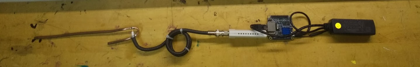
The parts, from left to right are:
- A copper j-pole antenna based on this design here
- The white usb thingy is an rtlsdr dongle which is the radio receiver part of the gizmo.
- The blue board it’s plugged into is the Orange Pi Zero (OPZ) which does the processing of the signals and the serving up via http.
- The black thing on the far right is a POE adapter. Which is why this setup can be run on a single ethernet cable.


I figure I’ll give it a coat of white paint and hide it somewhere near the top of the roof at some point, although based on the performance I’m seeing so far I think I’ve got some work to do in terms of antenna tuning and filtering.
But there’s something I find so satisfying about having a fully contained, web page hosting, air plane tracking tube that can be thrown on the end of a super long, cheap Ethernet cable anywhere on the house. Doing that part is hard though so this may be as far as this ever gets, if I’m being honest 🙂
DIY RF Network Analyser
So, strangely connected to my tube radio, is my need for a way to be able to properly measure antenna performance. Specifically high frequency antenna performance.
If money were no object, I’d likely just buy one of these bad boys and be done with it. Or, go completely nuts and by something like this. But money certainly is an object…or it does object(?), i dunno. Anyway I’m cheap as hell so over the years I’ve been buying assorted modules off ebay with only vague notions of how they’d be of use, in the hopes that one day I’d be able to build something that might just give useful data about a connected antenna. Well that day (or more specifically bunch of days spread over several months and or years) is today!
So, the short version of what a network analyser does, is that it sends out a signal that you can feed through your device, that then gets passed back into the analyser and it gives you a picture of how the signal changed. For instance, if you connected a straight piece of wire from the OUT to the IN, you’d expect to see a graph showing that the signal flowed through mostly unchanged. If you connected up some sort of filter, you’d expect to see the signal being reduced at the frequencies the filter was meant to filter out. Sounds simple right? You may see me occasionally referring to what I’ve built as either a spectrum analyser, or a network analyser, or even a vector network analyser. These are all flavours of the same things but with more or less features, ones I was never confident mine would have. So the changing of names was me effectively, managing my expectations…
Hardware
The key components of one of these units are, 1) A part that generates the test signal. A signal generator, if you will. 2) A part that quantifies signals in terms of power and maybe even phase. 3) Something to coordinate the generating and measuring that can spit out data in a meaningful way.
May I present
- The ADF4351. This is a 35 to 4400mhz signal source module that’s SPI controllable and cost just under 30$, which is actually kind of at the high end for most of my projects.
- The AD8302. This is a dual input device that takes two signals in and outputs a voltage proportional to the difference in magnitude and phase between them.
- The ESP32 OLED board. It’s an arduino compatible microcontroller board that has heaps of memory and speed that I figured were a requirement for this project. It also has SPI ability for controlling the signal generator and plenty of analog inputs for measuring the output from the AD8302 measurements. And it can connect via USB and pump the results to the PC for nice display options. This thing worked but gave me troubles that are probably worthy of a second post.
Here’s a crude schematic of how this thing is supposed to look

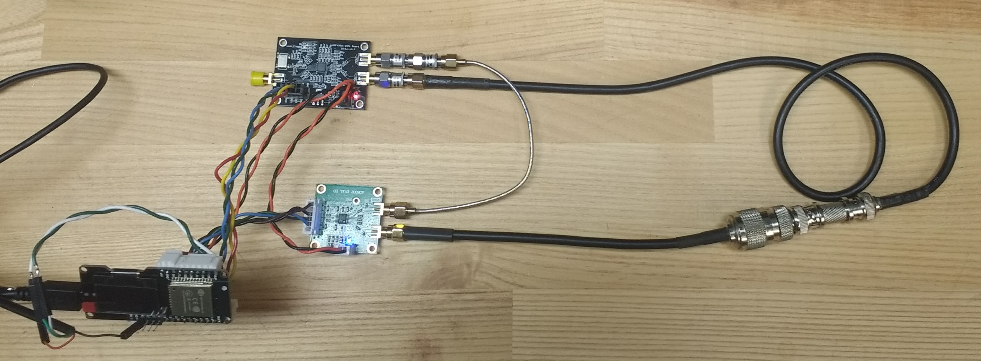
And here’s what that looks like all assembled together. In the test setup below, you can see the a short loop of thin hardline coax connecting the “reference” signal, from the generator (ADF4351) at the top, to the measuring board (AD8302) below. The second connection is just two pieces of straight coax with a bunch of couplers and adaptors inline because… that’s what I needed at the moment to connect two SMA connectors together.
Software
So, my standard caveat applies, this is by no means production code….like not even close. I’m almost too embarrassed to post it. It was a means to an end, and it shows. It’s posted here. I didn’t even give it the benefit of a fresh repo, it’s just thrown in with my pile of assorted arduino scraps.
Anyhow, it’s a two part application. The arduino half is what’s loaded on the ESP32 board. It’s job is to run the ADF4351 through a list of frequencies and then record the number on it’s three analog inputs that are coming from the AD8302, put them into a table and spit them out over the serial interface to the computer.
The other half is the python part. It’s job is to send instructions on what frequencies and how many steps to the arduino board and then wait for a response when its done. When it sees the json blob of data come back from the arduino it then puts it into a dataframe object and creates a nice shiny plot for the user to see. A plot like:
Result

What we’re looking at here is a plot of the hookup shown in the picture above, which is setup to measure the effect of a straight cable and a few adaptors. The green line is the vref output from the AD8302. Its giving you an effective max reference line. All measurements should fall between vref and 0. The blue line is magnitude, and it’s doing just about exactly as I expect. A straight cable shouldn’t really affect the magnitude of a signal much over that length, so a flat line makes sense. I’d expect a flat line near the 900 mark, but one cable has an additional 10dB attenuator which, according to the AD8302 datasheet, should make for a roughly 300 point difference, exactly what I see. Nice.
The orange line.. well, the orange line I had a much harder time explaining at first. Experienced RF engineers might roll their eyes at this point, but I was struggling because I thought that, like with magnitude, a short length of cable should not be fundamentally changing the signal, and it doesn’t. However, it does delay it. Which, in terms of phase, is actually the same thing. So it turns out that oscillating phase pattern is exactly what I should have expected. Its showing that as you sweep through a frequency range, the fixed time delay introduced by the difference in cable lengths will shift the signal by certain amount, changing it’s phase. Since the delay time is fixed, how much this delay affects the phase is dependent on the frequency/period of the signal.
In fact, based on my graph I should even be able to predict the difference in cable length based on the signal speed in that kind of cable and the frequencies where the signals come into phase (around the 900 mark in the graph. 900=in phase). I see crossings at the 250mhz, 400mhz, 550mhz and roughly every 150mhz from there on out. So I’m betting those are our 180 degree, or λ/2, points.


Sure enough, by my ruler, that extra loop of cable in the picture measures about 65cm. Not bad. So what that’s saying is that at the 150mhz intervals, the signal on the second path has been delayed enough that we’re now lined up with the next half-cycle of the wave and we’re effectively in phase again.
I think I’m going to stop here and plan another post about how this setup is actually useful for measuring an antenna.

Recent Comments